Explainers
Feb 5, 2026
From Real World To Little Triangles: A Guided Tour of Finite Element Analysis
Rafiq Omair
On your screen, there is a bridge that does not exist yet. A truck rolls across in simulation, the steel deck flexes by a few millimetres, and red patches appear where the stresses are highest. If something looks wrong, the engineer tweaks a dimension, runs the analysis again, and tries to make the red disappear long before anyone pours concrete or cuts steel.
That quiet process in the background is finite element analysis, usually shortened to FEA. It is one of the core tools in modern engineering, but from the outside it can feel like mysterious software that spits out colourful plots.
This article is your translator. The goal is to explain what FEA actually does, why it works, and how engineers use it, in plain language that a non-specialist can follow and an engineering student can build on.
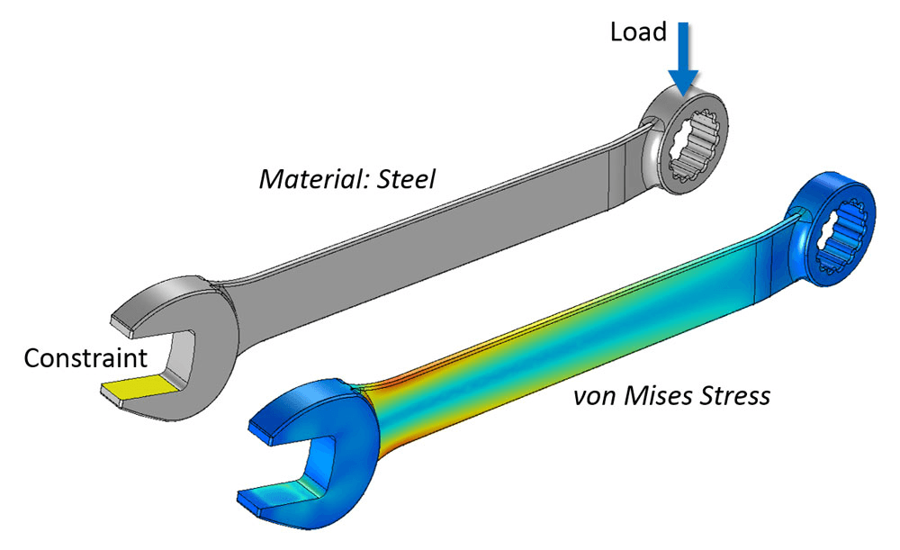
Fig 1. A simple FEA setup: fix one end, push on the other, and the simulation reveals where the wrench experiences the highest stress (von Mises stress).
The Big Idea: Break A Hard Problem Into Tiny Ones
Engineers constantly face questions like:
Will this bracket bend too much under load
Where is a part most likely to crack
How hot will this battery pack get during use?
In principl,e you can describe these problems with differential equations that come out of mechanics and heat transfer. In practice, for any real geometry, those equations are too hard to solve by hand.
Finite element analysis takes a different approach:
Instead of trying to solve one very complicated problem exactly, FEA cuts the object into many small, simple pieces and solves an approximate version on each piece.
You start with a continuous shape – a beam, a bracket, a section of wing – and you divide it into a large number of finite elements. Each element is a simple shape, often a triangle or quadrilateral in 2D, or a tetrahedron or brick in 3D. The corners of these elements are called nodes.
If you know how the object behaves at the nodes, you can approximate what happens inside each element. Connect all the elements back together, and you get an approximate solution for the whole part.
That is the core trick. The rest of FEA is bookkeeping and mathematics that make this idea precise and efficient.
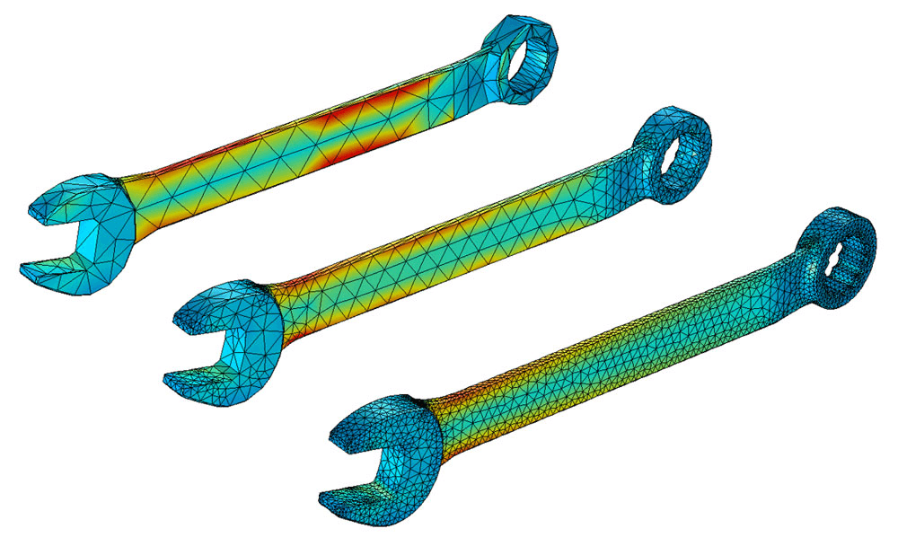
Fig 2. Coarse to fine mesh: more, smaller triangles usually means higher accuracy (especially near sharp corners), but it also increases compute time.
Step 1: From CAD Model To Mesh
In a typical workflow, an engineer begins with a geometry, often directly from a CAD model.
Simplify the geometry
Tiny fillets, cosmetic details, and fastener holes that are not important may be removed. Too much detail can make the analysis slow or unstable without improving accuracy.Choose the type of analysis
Are we interested in static deflection under a load, vibration frequencies, heat flow, or something that changes over timeGenerate a mesh
The software divides the geometry into elements. This pattern of elements and nodes is called a mesh.
Fine meshes with many small elements can capture details more accurately but require more computational effort. Coarser meshes run faster but may miss local effects. Part of the skill in FEA is choosing where you need finer detail and where you can get away with larger elements.
Step 2: Tell The Model What It Is Made Of
Next, the computer needs to know how the material behaves. For a simple structural analysis, you might specify:
Young’s modulus (how stiff the material is)
Poisson’s ratio (how it deforms sideways when stretched)
Yield strength (where permanent deformation begins)
For thermal problems, you care about thermal conductivity and heat capacity. For more advanced analyses, there may be complex material models for plastics, composites, or biological tissue.
This is where theory meets reality. If the material data is wrong or oversimplified, the results may look precise but be misleading. FEA can never be better than the assumptions you feed into it.
Step 3: Apply Loads And Boundary Conditions
To get a meaningful answer, you must also tell the model:
Where it is held or attached – these are boundary conditions. For instance, the base of a column might be fixed so it cannot move or rotate.
What loads it experiences – forces, pressures, temperatures, accelerations and so on.
Boundary conditions are easy to underestimate, but they are critical. Clamp a metal bar at both ends or just at one end, and you get very different patterns of stress under the same load. The same is true in the model.
At this point, the software has a discrete problem:
A large number of nodes whose movements or temperatures are unknown
Known relationships between those nodes based on material behaviour and element shapes
Known loads and constraints at specific locations
Now it is time to turn all of this into equations.
Step 4: Turning Physics Into A Giant System Of Equations
Behind the graphical interface, FEA uses the laws of physics, such as equilibrium of forces or conservation of energy, to build a huge system of linear or nonlinear equations.
In a structural problem, the basic relationship is often written in textbooks as:
stiffness × displacement = load
At the element level, you can derive a small stiffness matrix that links the forces at that element’s nodes to their displacements. The magic of FEA is in assembling all those element matrices into one gigantic global stiffness matrix that represents the entire structure.
For a model with tens or hundreds of thousands of nodes, this global system can involve millions of equations. No human solves that by hand. Efficient numerical algorithms and modern hardware make it practical.
The solver then crunches through this system to find the displacements at each node that satisfy the equations and the boundary conditions. From the displacements, the software can compute strains, stresses, and safety margins.
In thermal or fluid problems, the matrices look different, but the idea is similar. You are still using local element equations to build a global system that describes the field of interest.
Step 5: Post Processing – From Numbers To Insight
The raw output of an FEA solver is a large collection of numbers at the nodes and sometimes inside elements. On its own, that is not very intuitive.
Post-processing turns this data into plots and animations:
Colour maps of stress showing where a part is highly loaded
Contours of temperature in a heat sink
Animations of mode shapes in a vibration analysis
Plots of displacement magnitudes, often exaggerated to make small deformations visible
These images are not just pretty pictures. They help an engineer answer practical questions:
Is the maximum stress below the material yield strength with an adequate safety factor
Does a component deflect so much that it might jam or resonate
Are temperatures staying within safe limits for electronics or batteries?
If the answer is no, the design can be changed, and the analysis repeated long before prototypes are built.
What FEA Is Good At
Finite element analysis is powerful because it can handle:
Complex geometries that are impossible to treat with simple hand formulas
Multiple materials in one model, such as a composite structure with metal fasteners
Different physics are sometimes coupled, for example, thermo-mechanical problems, where temperature changes cause thermal stresses
What if studies where you test many variations quickly, such as changing thicknesses or materials
That is why you find FEA in aerospace companies, automotive design offices, medical device development, civil engineering, and even sports equipment design.
What FEA Cannot Do For You?
For all its power, FEA is not a magic truth machine.
Garbage in, garbage out
If the geometry, material data, or loads are wrong, the results will be wrong, no matter how pretty the pictures look.Approximation, not exactness
The mesh size, element type, and solver settings all influence accuracy. Engineers often run mesh convergence studies to check that refining the mesh does not change the results significantly.Judgment still required
Choosing realistic boundary conditions, interpreting stress concentrations, and deciding on safety factors all need human engineering judgment.
FEA is best seen as a very sophisticated calculator. It helps you explore designs and test hypotheses that would be impossible to check by hand, but it still depends on the quality of your questions and assumptions.
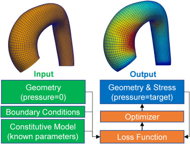
Fig 3. FEA can run in a loop: start with a geometry and assumptions, compare results to a target, then automatically adjust the design until it improves.
Why It Matters For Students And Curious Readers
For an engineering student, finite element analysis is both a subject and a practical skill:
It links theory from solid mechanics, materials, and numerical methods to real design work.
It appears in many courses, from structural analysis to vibrations and heat transfer.
It is a key item on the tool belt in many industries.
For a non-specialist, you do not need to know matrix algebra to appreciate the idea. FEA is how engineers test things in the computer before anyone spends money on a physical prototype or takes a safety risk.
The next time you see a colourful stress plot in a presentation or a simulation of a bridge bending in slow motion, you will know what is hiding underneath. A continuous object has been sliced into countless tiny elements, each obeying basic physics, and together they tell a story about how that design will behave in the real world.